2003 Honda Crv Front Suspension Diagram
Updated date:
2002-2006 Honda CRV Front Suspension Replacement/Repair (With Video)
-
-
-
-
Comment
Hardlymoving writes about do-it-yourself automobile maintenance on various makes and models.
Replacing the Components of the Honda CRV Front Suspension
This DIY involves the replacement or repair of the Honda CRV front suspension strut, lower ball joint, control arm, and sway bar link (stabilizer bar link). These are all the components of the front end suspension on the Honda CRV.
From my past work on Honda vehicles—as well as complaints from customers after I replaced their struts—I have concluded that if you replace the suspension struts, you should also replace the lower control arm, ball joint, and sway bar links, since they all seem to wear out together.
I will discuss the tools you are going to need, with a short video; show you the whole step-by-step procedure on a longer video; and then describe the same steps in writing.
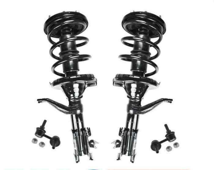
2002-2006 Honda CRV front struts with sway/stabilizer bar links.
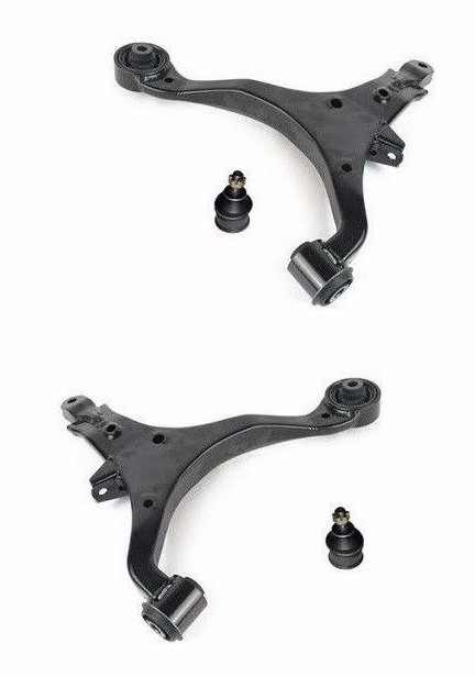
2002-2006 Honda CRV control arms and ball joints.
Here is a list of the special tools you'll need for this project. The short video below shows you these tools in action.
- A 36 mm CV axle shaft socket like this one. Put it on your impact driver to remove the axle nut. It works for many makes of cars.
- A large metal punch. This is nice to have to hammer the CV axle shaft through the wheel hub without damaging the CV axle threads.
- A standard ball joint press. It looks like a big C-clamp and applies the force to separate the ball joint from the steering knuckle. You can buy it (this one is good enough) or borrow it.
- A lower ball joint press adapter made especially for the shape of the Honda steering knuckle. It consists of three pieces. Two fit over the steering knuckle and ball joint and let you press the ball joint out; the third piece helps you press the new ball joint in. This adapter is available on Amazon (see below).
- A mechanical, air-driven, or electric impact driver. You will use it with a Phillips head attachment to remove the brake rotor screws.
The 17-minute video will provide you with visual step-by-step help for completing this repair. The steps are also described lower down in the article.
Removing the Brake Components and CV Axle Nut
1. Unbolt the brake line from the suspension strut.
2. Unbolt the ABS bracket from both the suspension strut and wheel well and detach the ABS clip.
Read More from AxleAddict
3. Remove the bottom bolt that secures the brake caliper to the caliper bracket and remove the caliper by sliding the caliper pin away from the caliper bracket.
4. Remove the two (2) bolts that secures the brake caliper bracket to the steering knuckle (with the brake pads attached) and remove the bracket off the brake rotor.
5. Remove the two screws that holds the brake rotor to the steering knuckle. If the rotor is stuck, hammer blows to the inside of the rotor may jar it loose; otherwise screw in a 12 mm bolt through one of the screw holes in the rotor until the rotor "pops" off.
6. Using an impact tool, remove the CV axle nut.
Video Tip on How to Remove a Honda Brake Rotor
Removing the CV Axle and Steering Knuckle
- Use a punch tool or impact hammer to push the CV axle through the wheel hub. Push down on the lower control arm and pull the axle out of the wheel hub splines.
- Support the CV axle up and away from the suspension using a bungee cord or strap attached to the CV shaft and the body of the car.
- Remove the cotter pin from the lower ball joint and unbolt the ball joint nut. Apply hammer blows to where the ball joint attaches to the lower control arm to force the ball joint to detach from the arm. The larger the hammer, the better the jarring force.
- Lift the steering knuckle with the attached ball joint away from the control arm.
Removing the Lower Control Arm
- Unbolt and detach the portion of the sway/stabilizer bar link attached to the control arm. If the shaft of the link spins with the link nut, the shaft can be held in place with a hex socket. I recommend using a box wrench to remove the link nut.
- Remove the two (2) bolts that hold the lower control arm to the chassis of the car. These 19-mm bolts are on very tight. If no impact tools are available, relieve the bolt torque using a breaker bar. Use a 1/2" wobble socket adapter to get the angle to torque off the rear bolt.
- Before pulling the control arm out, detach the sway / stabilizer link from the other side of the car to allow the sway bar to be lifted up and away from the control arm.
- Wiggle and remove the lower control arm.
Installing the New Lower Control Arm
- Apply penetrating oil to the mounting surfaces of the new control arm.
- Wiggle the control arm, aligning the control arm bushing holes with the holes of the control arm mounting points. A small pry bar will help with alignment along with a large-diameter dowel or screw driver.
- Insert the bolts and get the bolt threads started on the nuts of the control arm mounting points.
- After both bolts have been threaded, apply the final torque on the bolts with either an impact driver or breaker bar.
Removing and Installing the Ball Joint
Removal:
- Because the old ball joint is press-fitted into the steering knuckle under high pressure, you will generally need a ball joint press plus a Honda-specific ball joint removal and installation tool in order to remove and install the ball joint. Some ball joint service tool kits do have adapters that work with Honda ball joints.
- Position the Honda adapter with the cutout on top of the ball joint. Position the cylindrical adapter with the center hole over the ball joint shaft. Screw on the ball joint press tool connecting the two adapters.
- Using either an air or electric impact driver, torque the press tool screw which will push the ball joint out of the steering knuckle. If no impact driver is available, the press tool must be mounted and supported in a vice. Use a large ratchet wrench to turn the press tool shaft.
Installation:
- Clean the ball joint hole of the steering knuckle and apply a little grease to the hole.
- Position the new ball joint square onto the ball joint hole.
- Place the large-diameter Honda press tool adapter under the ball joint hole and attach the press tool; the top of the press tool goes over the top of the ball joint and the lower part of the press tool connects with the Honda press tool adapter.
- Using an air or electric impact driver, begin turning the press tool screw which will force the new ball joint into the hole. If no impact driver is available, the press tool must be mounted in a vice and the press tool screw tightened with a ratchet wrench. Continue turning the press tool screw until the top of the new ball joint is flush with the base of the steering knuckle ball joint hole.
- If the new ball joint came with a snap ring, install the snap ring at the base of the joint using snap ring pliers.
Installing the Steering Knuckle
- Connect the steering knuckle to the lower control arm by positioning the ball joint shaft onto the control arm ball joint hole.
- Screw on the new castle nut onto the ball joint shaft. Using a 1/2 socket wrench, torque down the castle nut and align the nut with the cotter pin hole in the ball joint shaft.
- Install the new cotter pin and bend in place.
- Apply grease to the outer CV axle shaft splines and push the axle shaft into the wheel hub. The hub can be turned left to right until the splines in the axle shaft line up with the wheel hub. Screw on the axle shaft bolt to prevent the shaft from popping out. The bolt need not be torqued down at this time.
- If replacing the sway/stabilizer link, unbolt the link from the sway bar using a combination of a box wrench and hex socket. The hex socket will prevent the shaft of the sway bar link from turning when apply torque to the sway bar nut.
Installing the Suspension Strut
- There should be two (2) arrows on the upper strut mount pointing towards each other. If not, turn the strut mount, using a pry bar or any metal bar braced between two of the strut mount studs, until the two arrows are pointing towards each other.
- Mount the new strut into the chassis by aligning the three (3) strut mount studs to the three (3) holes in the chassis.
- Screw on and tighten the new strut mount nuts.
- Connect the steering knuckle to the new strut by wiggling the two until the mounting holes are in alignment.
- Push in the strut bolts, screw on and tighten the strut nuts. If no impact driver is available, use a breaker bar to apply the final torque.
Installing the CV Axle Shaft Nut, Brake Components, and Tie Rod End
- Torque on the CV axle shaft nut until the original indentation mark on the nut is in alignment with the shaft groove. If no impact driver is available, prevent the hub from moving by using a long pry bar braced between the wheel hub lugs and the ground.
- Use a punch tool to bend the inner lip of the shaft nut into the CV axle shaft groove.
- Install the brake rotor onto the wheel hub and screw in the rotor screws. The screws need not be torqued down.
- Attach the tie rod end to the new strut, install and tighten the tie rod end nut and install the cotter pin.
- Bolt on the new or existing sway/stabilizer bar link to the control arm and sway bar.
- Mount the brake caliper bracket with the brake pads attached to the steering knuckle, line up with the mounting holes, then install and tighten the two (2) caliper bracket bolts.
- Re-attach the brake caliper to the caliper bracket by pushing the upper brake caliper pin into the bracket mounting hole.
- If the brake caliper does not mount over the brake pads, compress the caliper piston with either a C-clamp or a brake caliper piston compression tool.
- Install and tighten the lower brake caliper bolt.
Connecting the Wire and Hose
- Connect the ABS wire to the suspension strut and chassis of the car with the 10-mm bolts.
- Clip the ABS wire to the orange connector.
- Bolt the 12-mm brake hose line to the suspension strut.
This article is accurate and true to the best of the author's knowledge. Content is for informational or entertainment purposes only and does not substitute for personal counsel or professional advice in business, financial, legal, or technical matters.
Questions & Answers
Question: I have a CR-V 2003 with 97k mileage. There is a loose connection of a shaft I think that connects the cv joints which clicks when I accelerate or stop. Checking it, I jack up the front to lift both wheels. When I rotate the wheels there is a clicking sound coming from the loose connections of a bar in between the cv joints. What do you think is the problem with my CR-V's cv joints?
Answer: The noise is from worn out liquefied CV axle grease or worn out CV bearings in the CV inner or out cage. In the absence of high-speed centrifugal force (slow wheel rotation), when a bearing reaches it's peak, it drops into in CV cage when the cage advances ahead of the bearing. That's what's causing the clicking sound. If the grease had not liquefied or the bearings not worn out, the bearings would stay put and not be moving around. Hope my answer helps. The clicking sound does not indicate imminent failure of the CV axle. You can keep driving if you can tolerate the noise.
© 2018 hardlymoving
Related Articles
101 Cool Car Names for Guys
Whether you're a guy looking to name his car or even a girl looking for badass car names, here are 101 cool name ideas for your ride!
The Big List of Cool Car Names
If you're thinking about trying to come up with some cool car name ideas for your vehicle, then this is the article to give you a jump start on the process.
How A Block Heater Can Improve Your Winter Fuel Economy
If you often make short trips, especially to work and back, you've probably seen your fuel economy drop with the winter temperatures. A block heater can help you improve your fuel economy by pre-heating your engine and allowing it to burn fuel more efficiently.
Restore Your Headlights in 30 Minutes or Less
My 2008 Ford Edge headlights were cloudy and hazy! After a quick search online for replacements, I quickly found it was time to restore them or spend $500 to replace them. Follow along as I detail a quick, inexpensive process to get your headlights looking like new again without replacing them.
Posted by: alexaleexsasea0251725.blogspot.com
Source: https://axleaddict.com/auto-repair/2002-2006-Honda-CRV-Front-Suspension-Repair-Replacement

Post a Comment for "2003 Honda Crv Front Suspension Diagram"